- Define
- Profile
- Constrain
- Dimension
- Apply Modifiers
- Set Parameters
- Validate
- Test Part
- Repeat 2 - 8 for additional part features
Friday, November 5, 2010
New Blog
Thursday, September 10, 2009
C3D 2010 Leader Vertex Overrides
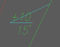
 Have you ever tried to anchor a text component to a line component which functioned as a landing to a leader?
And did you find that if you dragged the label over to its opposite side that the leader doesn't swap sides that it is anchored to automatically?
In the past we have handled this by creating two "duplicate" label styles, one behaving desirably when pulled to the left and the other behaving desirably when pulled to the right.

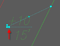
This is no longer necessary with Civil 3D 2010. Now we have the ability to apply a leader vertex override and add additional leader vertices to existing labels for creating jogs in the leader lines. With the diamond shaped grip, you can drag the leader vertex over and OSNAP it to the opposite side of the landing. Clicking on the minus sign removes the vertex override returning the leader to its original location. However clicking the plus sign allow you to define a jog in the leader line.
After applying such a leader override, be sure to use the original square shaped drag label grip to relocate the label components. Clicking on the circular grip will reset the overridden leader to its original location as does the minus sign. But clicking on the reset grip a second time will take the label to its original location out of drag state.
Tuesday, August 18, 2009
Autopopulating Custom Fields via VBA
Sunday, May 3, 2009
Non Style-based Civil 3D Customization
Pipe and Structure Libraries
Pipes and structures are three dimensional parametric parts. Not only must they be drawn, but values, extrusions, planes, and constraints must be configured as well. Creating a custom structure is not easy. If it were, then everyone would be making them and we would all be happy with our parts. There is a little bit of information available on various websites and blogs that can help with getting started. There are no books or classes on it unless you catch a quick one at AU. www.autodesk.com/au has some archived information that can be downloaded.
Custom Assembly Sets
Typical sections can be created and saved as blocks in the template or another DWG file. These blocks can be configured to be inserted and exploded via tool palettes. An advantage to setting up typical sections ahead of time in this manner is that code sets can be modified based on the subassemblies used in these sections. Also, pay items can be configured in these code sets for use with QTO.In 2010, we can define an "assembly set" for use with the new intersection tool. An assembly set actually comes from an XML file definition that declares what assembly is to be used in full section, left half section, right half section, and on the curb return for primary and secondary roads. The XML file also stores the path and filename where the assemblies reside.
Plan Production Template(s)
The plan production template or sheet settings template contains layout configurations for plan, profile or plan & profile sheets. The sheets are arranged along an alignment and match lines are inserted where needed. You would configure your layout with viewport types and scales, border, north arrow, legend, typical notes... anything particular you would want to see on each of the sheets produced.
There has always been a debate about how the plan production template customization should be served:
- Layouts in Civil 3D Styles Template - This option was preferred when plan production tools was initially released in 2007. The styles had to exist in the main template file so that they would exist in the newly created files. But this became unnecessary with the release of a service pack. Now, when sheet files are created, Civil 3D brings in the necessary styles.
- Layouts in One Sheet Settings Template - This option would involve one plan production template. This template contains all layout situations: border, scaled viewports, viewport arrangements, etc.
- Layouts in Multiple Sheet Settings Templates - When Civil 3D is creating sheets with this tool, each sheet file will contain all layout tabs from the sheet settings template. This is not ideal since this potentially could create a lot of useless layouts in one drawing. So a way to avoid the mess is to create one sheet settings template per configured layout.
Sheet Set Template(s) and Data Files
To fully implement sheet set manager, a custom sheet set data (DST) file should be set up. This file contains custom field values, block callout designations, and reference to a sheet set creation template with a configured layout tab and plot setup. The sheet set creation template does not require a configured viewport.Project Template(s)
The easiest part of Civil 3D configuration is creating a project template which is simply a named folder containing subfolders that represent standard directory structure in your Civil 3D project. Project templates are selected when creating a data shortcuts folder or when creating a Vault project.
QTO Customization
Civil 3D 2010 comes with a feature called QTO that enables you to extract pay items from your design. Pay items can be configured to code sets (corridors pavement quantities) and part lists (pipe network quantities).Pay item information can be configured in a block definition. Pay item information can manually assigned to a block, Civil 3D point, linework, and hatch patterns.
Civil 3D 2010 comes with some pay items files and categorization files already customized. However, they are not complete. Civil 3D can extract quantities for area (pavement and sod), linear measurement (pipes and curb), and individually counted items (trees and lightpoles).
Hopefully, this has got your wheels turning a bit with regard to completing your Civil 3D customization.
Wednesday, April 8, 2009
Civil 3D Jewels
A brief discussion concerning marker styles...
Marker styles are Civil 3D jewels that can used for emphasis in other display styles.
- Alignments can possess markers. Various marker styles can be assigned at different types of horizontal geometry intersections and other points of interest on alignments. Profiles can possess markers. Various marker styles can be assigned at different types of vertical geometry as well as vertical points of interest on alignments. Both alignments and profiles have a Markers tab that can be used to configure styles to these locations.
Marker styles are assigned to codes sets to delineate the locations of intersecting links which can be very important when constructing an assembly. - Marker styles can be configured to feature line styles for projection into views.
- Survey network styles use marker styles to delineate types of points observed in the field.
- Survey figure styles use marker styles to illustrate various points of interest along an observed linear feature.
- Marker styles can be configured to interference styles to mark where pipes are in conflict.
- Marker styles can be assigned to certain types of labels that are not a part of a label set.
- Marker styles can be selected at time of label creation.
I recommend the use of separate marker styles if the same shape is being utilized in multiple styles. For instance, if a circle is being used in both an alignment style as well as an assembly code set, use two separate styles so that you can scale them independently of each other.
Thursday, March 19, 2009
Short PVI Extensions
This is helpful to know if you are trying to build your perfect template. Peter Funk showed this to me when I was up in Manchester and my reaction was "duh" i.e. I couldn't believe I was doing it the hard way all this time.
Parcel Area – Commas
Click here to see the original blog: Parcel Area – Commas
Just to clarify, the trick involves six expressions:
- HundredsSize: IF({Parcel Area}>1000,0.0000000000000001,0.1/12)
- Hundreds: ({Parcel Area}/1000000-TRUNC({Parcel Area}/1000000))*1000
- ThousandsSize: IF({Parcel Area}>1000, IF({Parcel Area}<1000000,0.1/12,0.0000000000000001),0.0000000000000001)
- Thousands: {Parcel Area}/1000000
- MillionsSize: IF({Parcel Area}>1000000,0.1/12,0.0000000000000001)
- Millions: {Parcel Area}/1000000000
The label involves 4 text components: Parcel Name, Hundreds, Thousands, Millions
- Parcel Name is the parcel name.
- Hundreds is the area label configured for when parcel area is less than 1000.
- Thousands is the area label configured for when parcel area is more than 1000 and les than 1,000,000.
- Millions is the area label configured for when parcel area is more than 1,000,000.
The latter three components size themselves down to nothing as per the "Size" expressions listed above depending upon how their conditions check. In this example, labels will go in at 0.1" i.e. 0.1/12 as the expression reads. If you label using a smaller height like at 0.08", change each "Size" expression to use 0.08/12.
Think this is brilliant? Thank Christopher Fugitt who posted it at 12:31 AM this morning!
